A voltage reading tells you a number. An oscilloscope tells you a story.
Where a multimeter gives you one static figure, a scope plots voltage against time, continuously, so you actually see how a signal behaves. That difference matters more than most beginners realise. A motor might show a normal average current on a multimeter and still be throwing a nasty voltage spike every few milliseconds. A multimeter won’t catch that. A scope will show it plainly, right there on the trace.
For sparkies moving into fault-finding on control gear, VSDs, or anything with a switching circuit, learning how to use oscilloscopes properly is one of the more useful skills you can pick up. It’s not as intimidating as the front panel makes it look.
Setting Up Properly: This Step Gets Skipped a Lot
Before you touch a live circuit, compensate your probe. Every scope has a calibration output, usually a 1kHz square wave labelled “Probe Comp” or “Cal” on the front panel. Clip the probe tip onto it, connect the ground lead, and look at the waveform. Flat top, sharp corners — you’re compensated. Rounded edges or overshoot means the trimmer screw on the probe body needs a tweak. Skip this and every measurement after it is slightly wrong, even though the scope will look like it’s working fine.
Most probes ship set to 10x attenuation. Leave it there for general work. It reduces loading on the circuit and gives you more usable bandwidth. Switch to 1x only for very low-voltage signals, and remember your readings will need adjusting to match.
Grounding matters too, and not just for accuracy. A long, floppy ground lead adds inductance, which shows up as ringing on fast edges that isn’t actually in your circuit. For anything switching quickly, keep that lead as short as physically possible.
Reading the Screen
Three sections run the show: vertical, horizontal, and trigger.
Vertical (volts/div) sets how tall the waveform sits on screen. Horizontal (time/div) sets how many cycles you’re viewing. Trigger locks the display to a repeating point in the signal so the waveform holds still instead of drifting sideways, which it will do constantly if left untriggered.
A rough rule worth remembering: your scope’s bandwidth should be at least five times higher than the frequency you’re measuring. Go below that and fast edges start looking rounded even when the signal itself is clean. This trips people up more than anything else early on.
Auto-set is fine for a first look. But it rarely gives you the cleanest view for real diagnostic work, so expect to fine-tune the scale by hand once you’ve got a rough waveform on screen.
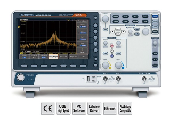
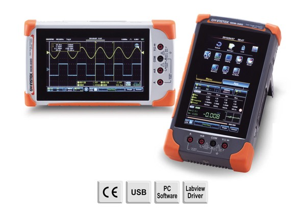
If you’re shopping around, Electrotest’s oscilloscope range covers benchtop and handheld models suited to workshop and field use, with bandwidth options for general electrical work through to RF diagnostics.
Common Signal Shapes Worth Knowing
Learn to recognise a handful of waveforms, and troubleshooting speeds up dramatically.
A clean sine wave usually points to mains or motor supply behaving normally
Square waves show up in switching circuits and digital logic
Sawtooth patterns often mean a charging capacitor or a timing circuit at work
Noisy, jagged traces layered on a clean signal usually mean interference, a dodgy ground, or a failing component nearby
Once you can spot these on sight, you stop guessing and start diagnosing.
Building the Skill Properly
Reading a manual only gets you so far. Hands-on time with real equipment, under someone who’s spent years pulling faults apart, is where this actually clicks. If that’s where you’re at, have a look at Electrotest’s training courses, several run with real test gear and cover the fundamentals properly rather than rushing through them.
And if you’d rather have someone experienced handle the diagnostic side entirely, Electrotest’s field services team carries out on-site testing across HV, partial discharge, and general electrical work, which is handy when the fault’s beyond what a bench scope alone can sort out.
Ask any electrician what they’d grab first to check current on a live circuit, and nine times out of ten they will point to the clamp meter hanging off their belt. The versatility of this device is what makes it popular. With a clamp meter, you can measure amps without cutting into a wire, and without shutting anything down; that’s the whole appeal, and it’s why the gadget has become standard kit across electrical work, HVAC, automotive diagnostics, and industrial
Understanding electrical rules helps keep people safe in their homes and workplaces. In Auckland, these rules are part of New Zealand law and make sure that electrical work is done properly. Electricity can be dangerous if it is not handled correctly. That is why there are codes that explain how wiring, switches, sockets and electrical gear should be installed and tested. If you are buying electrical supplies in Auckland or planning work in your home, you need to know how
Electrical safety is more important than ever, especially in homes, workplaces, and industrial settings. Faulty insulation in wiring can lead to shocks, short circuits, or even fires. That is why insulation resistance testing is essential. It helps identify weak or damaged insulation before any serious accidents occur. In New Zealand, electricians and building managers rely on proper testing to make sure installations are safe and compliant. Using the right procedures, tools, and quality electrical supplies in Auckland ensures circuits are correctly
Electrical work can be dangerous if it is not done safely. Without proper safety compliance, there could be shocks, fires, equipment damage, or even serious injury. Faulty wiring or damaged appliances can start accidents that are costly and dangerous. In this blog, we will explain electrical safety compliance in New Zealand so you can handle advanced electrical equipment. We will cover the rules, standards, requirements, and best practices that help keep people and property safe. By the end, you will
Share:
Frequently Asked Questions
No. A mid-range benchtop or handheld unit with 50–100MHz bandwidth covers most general electrical and control-circuit work. Save the higher bandwidth models for RF or fast digital signals.
DC coupling shows the full signal, including any DC offset. AC coupling filters that offset out, which is useful when you’re chasing a small ripple sitting on top of a larger DC voltage.
Your trigger isn’t set correctly. Adjust the trigger level until it sits on a consistent point in the signal, and the waveform should lock in place.
Check it whenever you swap probes between channels or scopes, and give it a quick look periodically even on gear you use daily. It only takes a moment.
Not really — they do different jobs. A multimeter is quicker for a single reading. A scope earns its keep when you need to see behaviour over time, like intermittent faults or switching noise.
It’s the ratio between the actual signal and what the probe passes through to the scope. A 10x probe divides the signal by ten, reducing circuit loading. Get the attenuation setting wrong on the scope and every reading will be out by a factor of ten.
Yes, Electrotest runs in-person courses using real gear rather than slides alone, which is a faster way to build confidence than working it out solo on the job.
An oscilloscope isn’t a mystery once you’ve compensated the probe, set your trigger, and matched the bandwidth to the job. Get those basics right, and the rest comes with practice. Ready to pick up a scope or sharpen your skills? Browse Electrotest’s oscilloscope range, book in on a training course, or call in the field services team for on-site help.
Stay in the loop for our new SPARKvue for Teachers Training Course launch!
Stay in the loop for our new Introduction to High Voltage Course launch!
Stay in the loop for our new UPS Installation & Commissioning Course launch!